A CASE STUDY
12 MVA TRANSFORMER - OLTC type FPE TC 546
A tap changer of this power transformer was operating on a narrow range of positions - from 7L to N only. DGA pointed to a problem with this unit and we tested the transformer using DV Power winding resistance and tap changer analyzer.
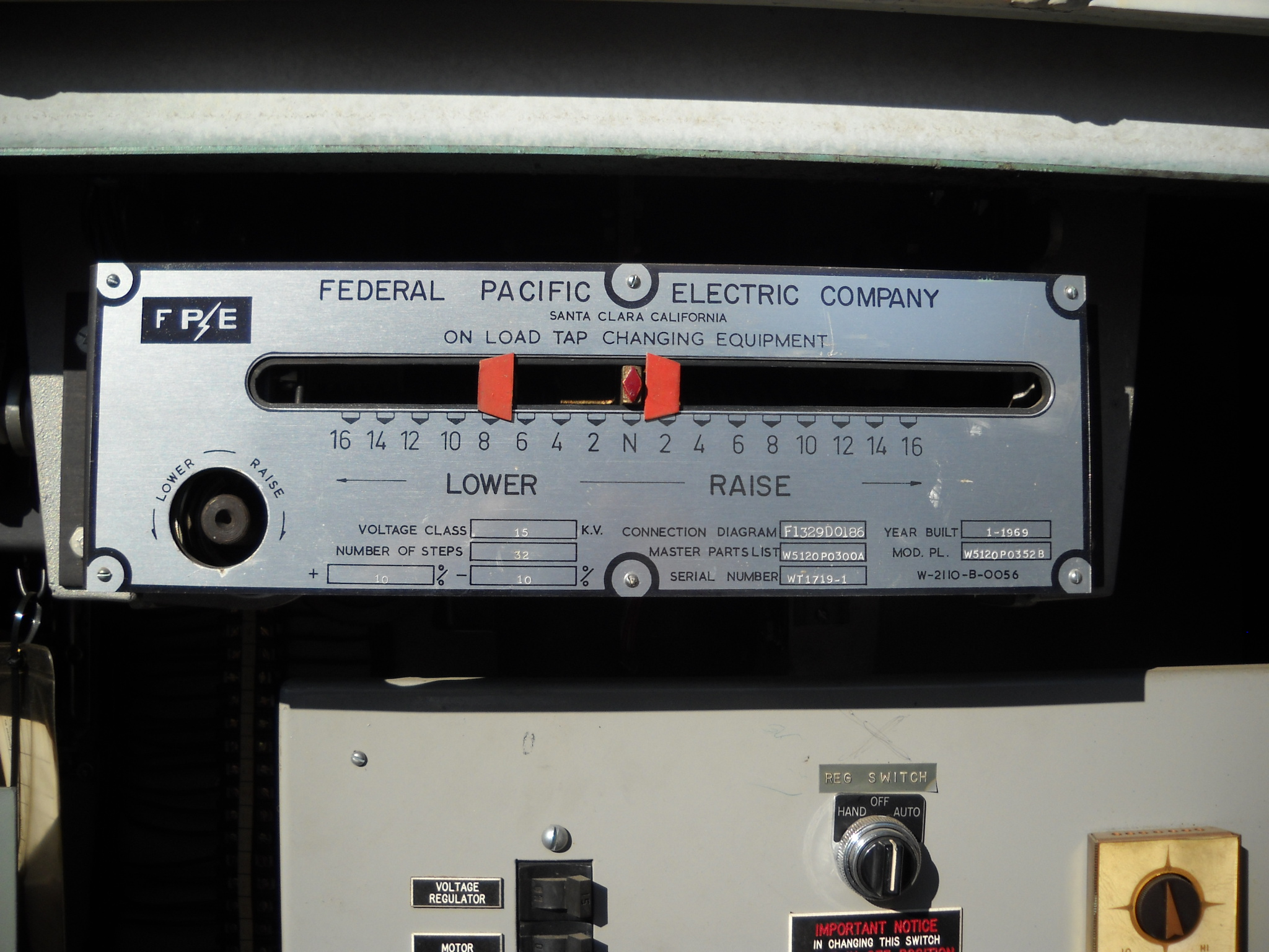 OLTC dial - showing the range of tap changer operation
The DVtest graph - or DRM, a dynamic current record - for a tap changer sweep from 16L to 16R positions showed a very confusing picture.
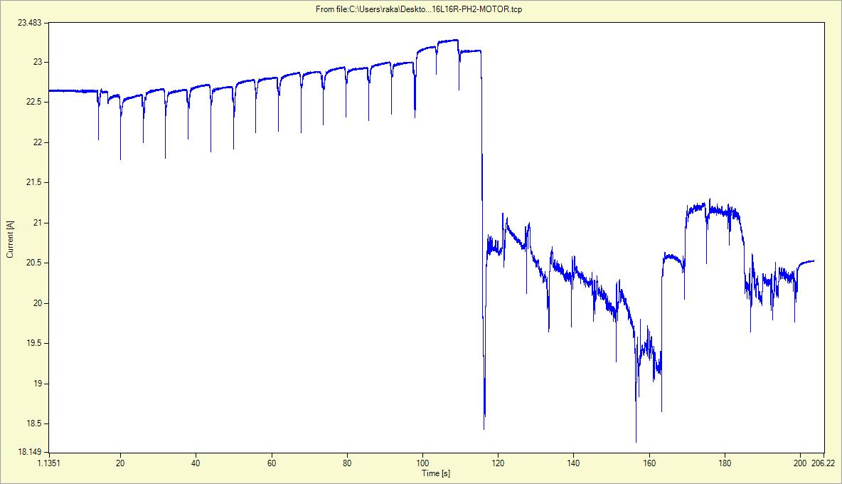
One side of the graph - position 16L to N - looked normal. DRM graph had consistent ripples and current values. The positions beyond the Neutral showed a very strange trace. The current record, where the value is lower than expected, in this case by 10%, indicates an increased resistance of the current path. This needed a verification, so we performed an additional test sweep from position 16R to 16L. The graph showed a "mirror image" issue:

All current traces of the positions 16R to N were in the pre set test current range of 25A; however, very rough and not consistent. Once the Neutral was reached the current jumped to the new value of 23-24 Amps. This current jump indicated a better resistance path in the LOWER region of the tap changer beyond the Neutral. These two graphs just confirmed that the problem is in the RAISE positions and since all the positions showed a common problematic trace, it was concluded that the reversal switch contact must be a culprit.
During the DVtest recording we also recorded the motor current trace. A very noisy squeaking sound, indicating some sort of a mechanical grinding was heard. The motor current trace showed an increase of the energy needed for the motor to operate. This noise together with the current increase disappeared after the Neutral position was passed.

This unit was scheduled for a maintenance / repair based on our findings, and following the repair, the report and photographs explain the problems found in the unit.
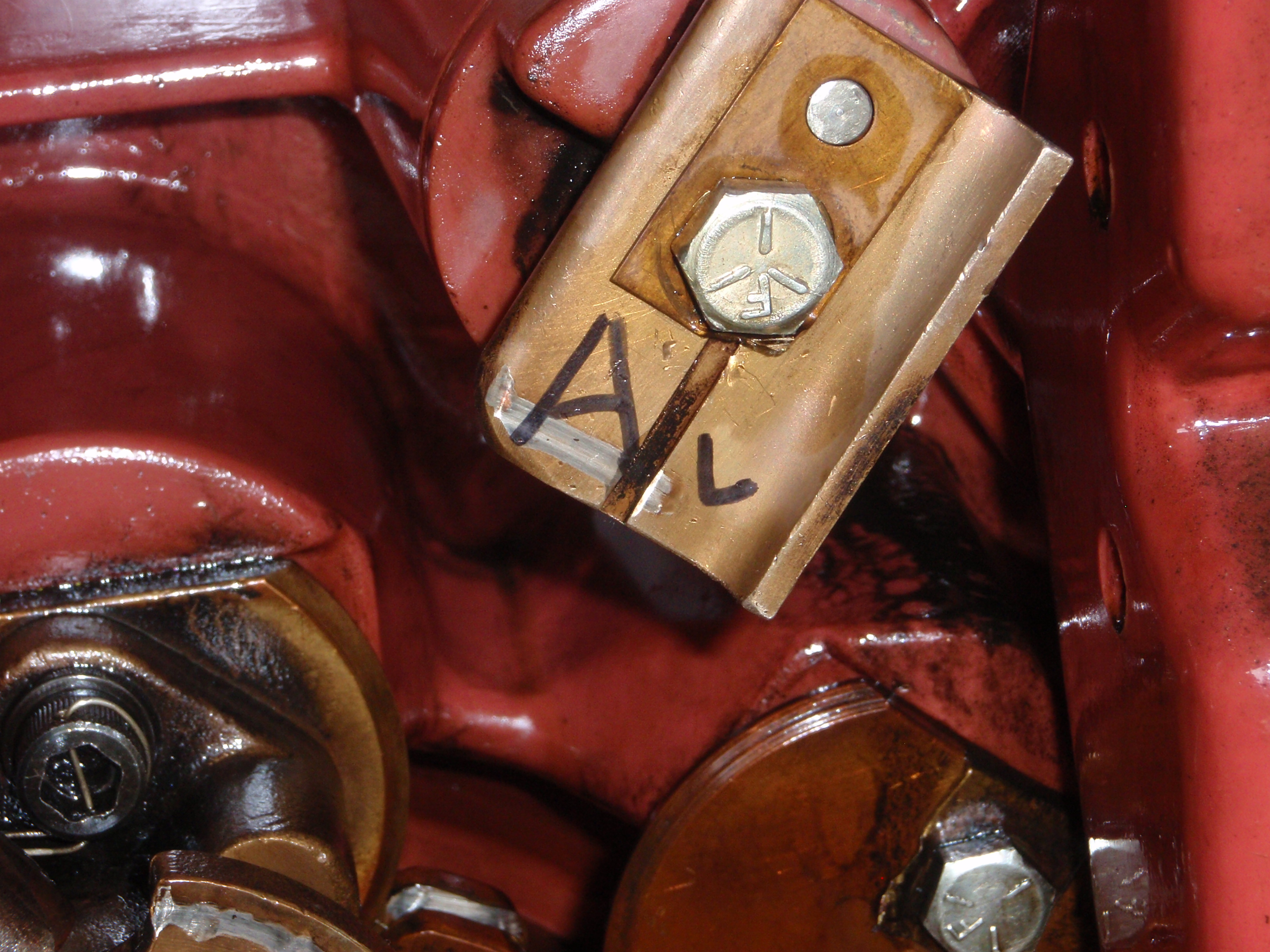
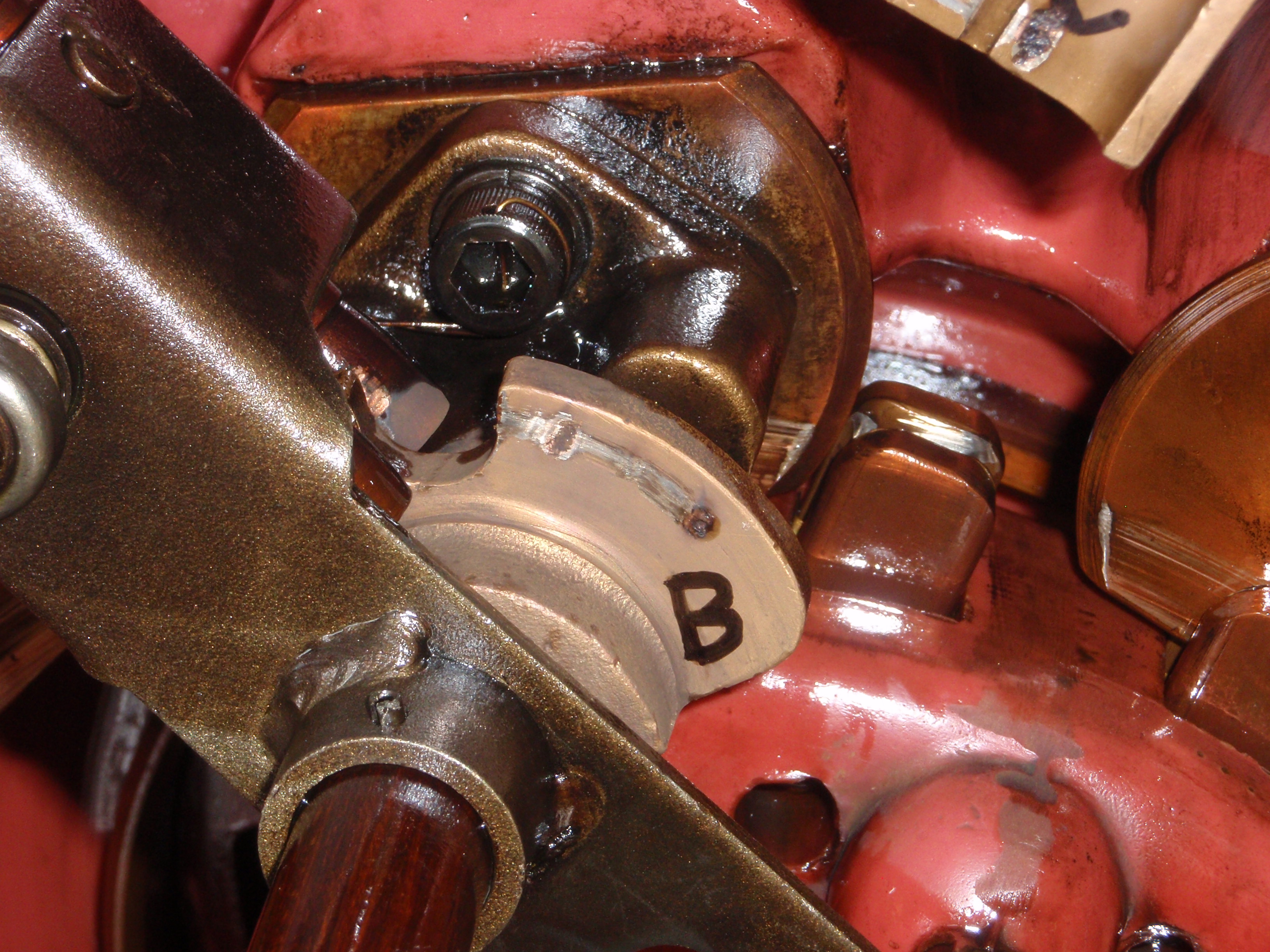
Once opened, resistances were tested from collector rings to stationary contacts, through the rotor. A phase 1000 u-ohms, B phase 885 u-ohms, and C phase 180 u-ohms was measured. This is a huge discrepancy for A and B phases.
Reversal switch contact pitting was found, and those contacts were replaced. The report states also the following maintenance tasks performed:
Updated diverters, installed shunt straps to all 6 diverters, replaced all
arcing contacts, because of unusual cracking in face of contacts. Re-aligned
face to face mating by bending arms until flush. Re-tensioned drive chain and
drilled new pin, Replaced 2 diverter barriers
Replaced rotor bearings and replaced stationary contact locking tabs.